Anthem MRX SLM Bruksanvisning
Les nedenfor 📖 manual på norsk for Anthem MRX SLM (58 sider) i kategorien Mottaker. Denne guiden var nyttig for 13 personer og ble vurdert med 4.5 stjerner i gjennomsnitt av 2 brukere
Side 1/58
O P E R A T I N G M A N U A L
MRX SLM
A/V RECEIVER

II
I M P O R T A N T S A F E T Y I N S T R U C T I O N S
CAUTION: TO REDUCE THE RISK OF ELECTRIC SHOCK, DO NOT REMOVE THE COVER.
NO USER-SERVICEABLE PARTS INSIDE. REFER SERVICING TO QUALIFIED SERVICE PERSONNEL
RISK OF ELECTRIC SHOCK DO NOT OPEN
The lightning ash with arrowhead
symbol within an equilateral
triangle is intended to alert the user
to the presence of uninsulated
“dangerous voltage” within the
product’s enclosure that may be of
sucient magnitude to constitute a
risk of electric shock to persons.
The exclamation point within an
equilateral triangle is intended to
alert the user to the presence of
important operating and maintenance
(servicing) instructions in the literature
accompanying the appliance.
1. Read these instructions.
2. Keep these instructions.
3. Heed all warnings.
4. Follow all instructions.
5. Do not use this apparatus near water.
6. Clean only with a dry cloth.
7. Install in accordance with the manufacturer’s instructions.
8. Do not install near any heat sources such as radiators, heat registers, stoves or other apparatus (including ampliers) that produce heat.
9. Do not defeat the safety purpose of the polarized or grounding-type plug. A polarized plug has two blades with one wider than the
other. A grounding-type plug has two blades and a third grounding prong. The wide blade or the third prong is provided for your safety.
When the provided plug does not t into your outlet, consult an electrician for replacement of the obsolete outlet.
10. Protect the power cord from being walked on or pinched, particularly at plugs, convenience receptacles and the point where
they exit from the apparatus.
11. Only use the attachments/accessories specied by the manufacturer.
12. Use only with a cart, stand, tripod, bracket or table specied by the manufacturer, or sold with the apparatus.
13. Unplug this apparatus during lightning storms or when unused for long periods of time.
14. Refer all servicing to qualied service personnel. Servicing is required when the apparatus has been damaged in any way, such
as power supply cord or plug is damaged, liquid has been spilled or objects have fallen into the apparatus, the apparatus has
been exposed to rain or moisture, does not operate normally, or has been dropped.
15. Do not operate this apparatus at an altitude over 6561 ft / 2000 m.
CAUTION

II
WARNING: To reduce the risk of re or electric shock, do not expose this apparatus to rain or
moisture. Avoid installing this unit where foreign objects may fall onto this unit and/or this unit may
be exposed to liquid dripping or splashing. On the top of this unit, do not place:
• Burning objects (i.e. candles), as they may cause re, damage to this unit, and/or
personal injury.
• Containers with liquid in them, as they may fall and liquid may cause electrical shock to
the user and/or damage to this unit.
Apparatus shall not be exposed to dripping or splashing and no objects lled with liquids, such as
vases, shall be placed on the apparatus.
Install it away from direct sunlight, heat sources, vibration, dust, moisture, and/or cold.
Do not cover this unit with a newspaper, tablecloth, curtain, etc. in order not to obstruct heat
radiation. If the temperature inside this unit rises, it may cause re, damage to this unit, and/or
personal injury.
Install this unit near the AC outlet and where the AC power plug can be reached easily.
This unit is not disconnected from the AC power source when it is turned o. This state is called
the standby mode. In this state, this unit is designed to consume a very small quantity of power.
To completely disconnect this apparatus from the AC mains, disconnect the power supply cord
plug from the AC receptacle.
NOTE: This product is not an auto voltage receiver. Connect only to the prescribed AC source as
shown above the AC inlet of the receiver. i.e., 120VAC 60Hz (250W maximum) or 220-240VAC
50Hz, 1-phase (250W maximum).
CAUTION: These servicing instructions are for use by qualied service personnel only. To reduce
the risk of electric shock, do not perform any servicing other than that contained in the operating
instructions, unless you are qualied to do so.
CAUTION: Changes or modications to this equipment not expressly approved by Paradigm
Electronics for compliance could void the user’s authority to operate this equipment.
FCC WARNING: Changes or modications not expressly approved by the party responsible for
compliance could void the user’s authority to operate the equipment.
This equipment has been tested and found to comply with the limits for a class B digital device,
pursuant to part 15 of the FCC Rules. These limits are designed to provide reasonable protection
against harmful interference in a residential installation. This equipment generates, uses and can
radiate radio frequency energy and, if not installed and used in accordance with the instructions,
may cause harmful interference to radio communications. However, there is no guarantee
that interference will not occur in a particular installation. If this equipment does cause harmful
interference to radio or television reception, which can be determined by turning the equipment
o and on, the user is encouraged to try to correct the interference by one or more of the
following measures:
• Reorient or relocate the receiving antenna.
• Increase the separation between the equipment and the unit.
• Connect the equipment into an outlet on a circuit dierent from that to which the unit
is connected.
• Consult the dealer or an experienced radio / TV technician for help.

III
PROPOSITION 65 WARNING (California only)
This product contains a chemical known to the State of California
to cause cancer and birth defects or other reproductive harm.
For more information go to www.p65warnings.ca.gov
RED Directive 2014/53/EU
This product may be operated in the following countries;
AT BE CZ DK FI
FR DE GR HU IE
IT NL PL PT SK
ES SE GB NO CH
Indoor use only.
Maximum RF Power in Operating Frequency Bands
Frequency Bands, (GHz) 2.40-2.48
4.27 mW 32.35 mW
5.18-5.24 5.26-5.35 5.48-5.7
Maximum Peak Output Power
USA CANADA
FCC Information (For US customers)
1. IMPORTANT NOTICE: DO NOT MODIFY THIS PRODUCT
This device complies with Part 15 of the FCC Rules. Operation is subject to the following two conditions: (1) this device may not cause
harmful interference, and (2) this device must accept any interference received, including interference that may cause undesired
operation. This product does not contain any user serviceable components. Any unauthorized product changes or modifications will
invalidate warranty and all applicable regulatory certifications and approvals, including authority to operate this device.
2. CAUTION
•To comply with the FCC/IC RF exposure compliance requirements, a separation distance of at least 20 cm must be
maintained between the antenna of this device and all persons.
•This device and its antenna must not be co-located or operating in conjunction with any other antenna or transmitter.
•This transmitter must not be co-located or operating in conjunction with any other antenna or transmitter.
•Operations in the 5.15 - 5.25 GHz band are restricted to indoor usage only.
•For operation within 5.15 - 5.25 GHz / 5.25 - 5.35 GHz / 5.47 - 5.725 GHz frequency range, it is restricted to indoor
environment.
• This device meets all the other requirements specified in Part 15E, Section 15.407 of the FCC Rules.
3. COMPLIANCE INFORMATION
• Product Name:
MRX SLM : AV Receiver
IC Information (For Canadian customers)
1. PRODUCT
CONTAINS TRANSMITTER MODULE IC: 20504-ST1955
For Canadian customers/Pour les clients Canadiens: CAN ICES-003(B)/NMB-003(B) This Class B digital apparatus complies with
Canadian ICES-003 and RSS-247. Operation is subject to the following two conditions: (1) This device may not cause harmful
interference, and (2) This device must accept any interference received, including interference that may cause undesired operation.
2. CAUTION
This product complies with RSS-210 of Innovation, Science and Economic Development Canada. The installer of this radio
equipment must ensure that the product is located such that it does not emit RF field in excess of Health Canada limits for the
general population: consult Safety Code 6, obtainable from Health Canada´s We site www.hc-sc.gc.ca/rpb. As mentioned before,
the installer cannot control the antenna orientation. However, they could place the complete product in a way that causes the
problem mentioned above. The device for operation in the band 5150-5250 MHz is only for indoor use to reduce the potential for
harmful interference to co-channel mobile satellite systems. Be advised that high-power radars are allocated as primary users (i.e.
priority users) of the bands 5250-5350MHz and 5650-5850MHz and that these radars could cause interference and/or damage to
LE-LAN devices. Changes or modifications not expressly approved by the party responsible for compliance could void the user's
authority to operate the equipment.
The band 5150–5250 MHz is only for indoor use to reduce the potential for harmful interference to co-channel mobile satellite
systems. For devices with detachable antenna(s), the maximum antenna gain permitted for devices in the bands 5250-5350 MHz
and 5470-5725 MHz shall be such that the equipment still complies with the e.i.r.p. limit. For devices with detachable antenna(s),
the maximum antenna gain permitted for devices in the band 5725-5850 MHz shall be such that the equipment still complies with
the e.i.r.p. limits as appropriate; and Where applicable, antenna type(s), antenna models(s), and worst-case tilt angle(s) necessary
to remain compliant with the e.i.r.p. elevation mask requirement set forth in section 6.2.2.3 of RSS-247 shall be clearly indicated.
Informations sur IC (pour les clients canadiens)
1. APPAREIL
CONTIENT MODULE ÉMETTEUR IC: 20504-ST1955
Cet appareil numérique de classe B est conforme aux normes canadiennes ICES-003 et RSS-247. L’exploitation est soumise aux
deux conditions suivantes : (1) Cet appareil ne doit pas provoquer d'interférences nuisibles, et (2) Cet appareil doit accepter toute
interférence reçue, y compris les interférences susceptibles de provoquer un fonctionnement indésirable.
2. ATTENTION
Ce produit est conforme au RSS-210 d'Innovation, Sciences et Développement économique Canada. L'installateur de cet
équipement radio doit s'assurer que le produit est situé de telle sorte qu'il n'émet pas de champ RF dépassant les limites de Santé
Canada pour la population générale : consulter le Code de sécurité 6, disponible sur le site We de Santé Canada www.hc-sc..gc.-
ca/rpb. Comme mentionné précédemment, l'installateur ne peut pas contrôler l'orientation de l'antenne. Cependant, ils pourraient
placer le produit complet d’une manière qui provoque le problème mentionné ci-dessus. L'appareil destiné à fonctionner dans la
bande 5 150-5 250 MHz est uniquement destiné à une utilisation en intérieur afin de réduire le risque d'interférence nuisible aux
systèmes par satellite mobiles co-canaux. Sachez que les radars de haute puissance sont attribués en tant qu'utilisateurs
principaux (c'est-à-dire utilisateurs prioritaires) des bandes 5 250-5 350 MHz et 5 650-5 850 MHz et que ces radars pourraient
provoquer des interférences et/ou endommager les appareils LE-LAN. Les changements ou modifications non expressément
approuvés par la partie responsable de la conformité pourraient annuler le droit de l'utilisateur à utiliser l'équipement.
La bande 5 150–5 250 MHz est uniquement destinée à une utilisation en intérieur afin de réduire le risque d'interférences nuisibles
aux systèmes mobiles par satellite dans le même canal. Pour les appareils dotés d'antenne(s) amovible(s), le gain d'antenne
maximal autorisé pour les appareils dans les bandes 5 250-5 350 MHz et 5 470-5 725 MHz doit être tel que l'équipement reste
conforme à la p.i.r.e. limite. Pour les appareils dotés d'antenne(s) amovible(s), le gain d'antenne maximal autorisé pour les appareils
dans la bande 5 725-5 850 MHz doit être tel que l'équipement reste conforme à la p.i.r.e. limites, le cas échéant ; et Le cas échéant,
le(s) type(s) d'antenne, le(s) modèle(s) d'antenne et le(s) angle(s) d'inclinaison dans le pire des cas nécessaires pour rester conforme
à la p.i.r.e. L’exigence relative au masque d’élévation énoncée à la section 6.2.2.3 du RSS-247 doit être clairement indiquée.
ENGLISH
1. DECLARATION OF CONFORMITY
Our product complies with the relevant provisions of the EU/EC directives as follows:
Radio Equipment Directive 2014/53/EU.
2. IMPORTANT NOTICE: DO NOT MODIFY THIS PRODUCT
This product, when installed as indicated in the instructions contained in this manual,
meets EU requirements directive requirements. Modification of the product could
result in hazardous Radio and EMC radiation.
3. CAUTION
Separation distance of at least 20 cm must be maintained between this product and
all persons. This product and its antenna must not be co-located or operating in
conjunction with any other antenna or transmitter.
•5,150 – 5,350 MHz is restricted to indoor use only.
DEUTSCH
1. ÜBEREINSTIMMUNGSERKLÄRUNG
Unsere Produkte unterliegen den Bestimmungen der folgenden EG/EU-Richtlinien:
Funkgeräterichtlinie 2014/53/EU.
2. WICHTIGER HINWEIS: NEHMEN SIE KEI VERÄNDERUNGEN AN
DIESEM PRODUKT VOR
Wenn dieses Produkt entsprechend dieser Bedienungsanleitung aufgebaut wird,
entspricht es den Anforderungen der R&TTE-Richtlinie. Veränderungen am Produkt
können zu gefährlicher Funk- und EMV-Strahlung führen.
3. VORSICHT
Zwischen dieses Produkts und Personen muss ein Schutzabstand von 20 cm
eingehalten werden. Dieses Produkt und seine Antenne dürfen nicht neben anderen
Antennen oder Sendern aufgestellt oder zusammen mit ihnen verwendet werden.
•5.150 – 5.350 MHz darf nur in geschlossenen Räumen verwendet werden.
FRANÇAIS
1. DECLARATION DE CONFORMITE
Nos produits sont conformes aux dispositions des directives CE/UE comme suit ;
Directive sur les équipements radio 2014/53/UE.
2. MISE EN GARDE IMPORTANTE : NE JAMAIS MODIFIER CE PRODUIT
Si toutes les consignes indiquées dans ce mode ont été respectées pendant son
installation, ce produit est conforme aux directives R&TTE. Toute modification du
produit risquerait alors de générer des radiations radio et EMC dangereuses.
3. ATTENTION
L’appareil devra être située à une distance de 20 cm au moins des personnes. Ce
produit ainsi que son antenne ne devront en aucun cas être utilisés à proximité d’une
autre antenne ou transmetteur.
•5 150 - 5 350 MHz est limité à une utilisation en intérieur uniquement.
ITALIANO
1. DICHIARAZIONE DI CONFORMITÀ
I nostri prodotti sono conformi a quanto previsto dalle direttive EC/EU, come
specificato di seguito: Direttiva sulle apparecchiature radio 2014/53/UE.
2. AVVERTENZA IMPORTANTE: NON MODIFICA QUESTO PRODOTTO
Se installato come indicato nelle istruzioni del presente manuale, questo prodotto
soddisfa i requisiti della direttiva R&TTE. Eventuali modifiche apportate al prodotto
potrebbero causare pericolose radiazioni radio ed EMC.
3. ATTENZIONE
È necessario mantenere una distanza minima di 20 cm tra questo prodotto e le
persone. Questo prodotto e la relativa antenna non devono essere posizionati in
prossimità di altre antenne o trasmettitori e non devono essere utilizzati
congiuntamente a questi ultimi.
•La frequenza 5,150 – 5,350 MHz è limitata al solo uso interno.
ESPAÑOL
1. DECLARACIÓN DE CONFORMIDAD
Nuestros productos cumplen las disposiciones de las directivas de la CE/UE
siguientes: Directiva sobre equipos de radio 2014/53/UE.
2. NOTA IMPORTANTE: NO MODIFIQUE ESTE PRODUCTO
Este producto, si es instalado de acuerdo con las instrucciones contenidas en este
manual, cumple los requisitos de la directiva R&TTE. La modificación del producto
puede producir radiación de Radio y EMC peligrosa.
3. PRECAUCIÓN
Se debe mantener una separación de al menos 20 cm del producto y las
personas.Este producto y su antena no debe instalarse ni utilizarse conjuntamente
con otra antena o transmisor.
•5,150 – 5,350 MHz está restringido al uso en interiores solamente.
NEDERLANDS
1. EENVORMIGHEIDSVERKLARING
Onze producten volgen de voorwaarden van de EG/EU-richtlijnen zoals volgt;
Richtlijn radioapparatuur 2014/53/EU.
2. BELANGRIJKE MEDEDELING: BRENG AAN D PRODUCT GEEN
AANPASSINGEN AAN
Dit product, indien geïnstalleerd volgens de aanwijzingen in deze gebruiksaanwijzing,
voldoet aan de vereisten van de R&TTE-richtlijn. Aanpassing van dit product kan
gevaarlijke radio- en EMC-straling tot gevolg hebben.
3. LET OP
Houd tussen en personen altijd een afstand van tenminste 20 cm aan. Dit product en
zijn antenne mogen niet in de buurt van een andere antenne of zender worden
geplaatst of in combinatie daarmee worden gebruikt.
•5.150 – 5.350 MHz is beperkt tot alleen binnenshuis gebruik.
SVENSKA
1. ÖVERENSSTÄMMELSESINTYG
Våra produkter uppfyller följande föreskrifter i EC/EU-direktiv: Radioutrustningsdirek-
tiv 2014/53/EU.
2. VIKTIGT: APPARATEN FÅR INTE MODIFIERAS
Under förutsättning att apparaten installeras enligt anvisningarna i denna
bruksanvisning, uppfyller denna kraven i R&TTE-direktivet. Ev. modifiering av
apparaten kan resultera i farlig radio- och elektromagnetisk strålning.
3. FÖRSIKTIGT
Se till att det finns ett avstånd på minst 20 cm mellan apparatens och personer i
omgivningen. Apparaten och dess antenn får inte placeras eller användas i närheten
av andra antenner eller sändare.
•5 150 – 5 350 MHz är begränsat till inomhusbruk.
РУССКИЙ
1. СЕРТИФИКАТ СООТВЕТСТВИЯ
Наши продукты соответствуют следующим положениям директив ЕК/ЕС: Директива по
радиооборудованию 2014/53/ЕС.
2. ВАЖНО! НЕ ВНОСИТЕ ИЗМЕНЕНИЯ В ДАННЫЙ ПРОДУКТ
Данный продукт отвечает требованиям директив R&TTE, если установлен согласно
инструкциям из настоящего руководства. Внесение любых изменений в продукт
может привести к появлению опасного электромагнитного излучения.
3. ПРЕДУПРЕЖДЕНИЕ
Расстояние между данным изделием и людьми должно составлять не менее 20 см. Не
используйте данный продукт и его антенны рядом с другими антеннами или
передатчиками. Не используйте данное устройство с антеннами сторонних
производителей.
• внутри Диапазон частот 5,150 - 5,350 МГц предназначен для использования только
помещений.
POLSKI
1. DEKLARACJA ZGODNOŚCI
Nasze produkty zgodnie z postanowieniami KE/UE, tj. Dyrektywa w sprawie urządzeń
radiowych 2014/53/UE.
2. UWAGA: MODYFIKACJA TEGO URZĄDZENIA JEST ZABRONIONA
Po zainstalowaniu zgodnie z instrukcjami zawartymi w niniejszej instrukcji obsługi
urzadzenie to bedzie spełniac wymogi dyrektywy R&TTE. Wprowadzanie modykacji do
tego urzadzenia moze skutkowac powstaniem niebezpiecznego promieni owania
elektromagnetycznego oraz radiowego.
3. OSTRZEŻENIE
Miedzy tego produktu i wszelkimi osobami musi byc zachowana odległosc przynajmniej 20
cm. Urzadzenia wraz z antena nie mozna instalowac w połaczeniu z inna antena lub
nadajnikiem.
• 5.150 – 5.350 MHz to czestotliwosc ograniczona do uzytkowania jedynie w
pomieszczeniach.
DANISH
1. ERKLÆRING OM OVERHOLDELSE
Vores produkter lever op til bestemmelserne i følgende EF-/EU-direktiver;
Radioudstyrsdirektiv 2014/53/EU.
2. VIGTIG BEMÆRKNING: DU MÅ IKKE ÆNDRE DETTE PRODUKT
Når dette produkt installeres som beskrevet i instruktionerne i denne manual,
overholder det kravene i R&TTE-direktivet. Ændring af produktet kan medføre farlig
radio- og EMC-stråling.
3. FORSIGTIG
Der skal opretholdes en afstand på mindst 20 cm mellem produktet og alle personer.
Dette produkt og dets antenne må ikke placeres i nærheden af eller fungere sammen
med andre antenner eller sendere.
• 5.150 – 5.350 MHz er begrænset til udelukkende indendørs brug.
NORWAY
1. SAMSVARSERKLÆRING
Produktene våre følger bestemmelsene i følgende EC/EU-direktiv: Radioutstyrsdirek-
tiv 2014/53/EU.
2. VIKTIG MERKNAD: IKKE MODIFISER DETTE PRODUKTET
Når dette produktet er montert som angitt i instruksjonene i denne håndboken,
oppfyller det kravene i R&TTE-direktivet. Modifisering av produktet kan resultere i
farlig radio- og EMC-stråling.
3. OBS!
Det må opprettholdes en avstand på minst 20 cm mellom dette produktet og alle
personer. Dette produktet og antennen må ikke plasseres på samme sted som eller
brukes i forbindelse med andre antenner eller sendere.
• 5.150 – 5.350 MHz er kun begrenset til innendørs bruk.
• DECLARATION OF CONFORMITY
Our products following the provisions of EC/EU directives, that as follows;
LVD: 2014/35/EU
EMC: 2014/30/EU
ErP: EC regulation 1275/2008, EU regulation 801/2013, and its
framework directive 2009/125/EC
RED: 2014/53/EU
RoHS: 2011/65/EU
WEEE: 2012/19/EU
Paradigm Electronics Inc.
205 Annagem Blvd. Mississauga, ON L5T 2V1 Canada
IIEC 62368-1
• CONTAINS TRANSMITTER MODULE FCC ID: 2AJYB-ST1955
This product complies with Part 15 of FCC Rules. Operation is subject to the following two conditions: (1) this product may not cause harmful interference, and
(2) this product must accept any interference received, including interference that may cause undesired operation.
Paradigm Electronics Inc.
205 Annagem Blvd. Mississauga, ON L5T 2V1 Canada
4. NOTE
This product has been tested and found to comply with the limits for a Class B digital device, pursuant to Part 15 of the FCC Rules. These limits are designed to provide reasonable protection against harmful interference in a residential installation. This product
generates, uses and can radiate radio frequency energy and, if not installed and used in accordance with the instructions, may cause harmful interference to radio communications. However, there is no guarantee that interference will not occur in a particular installation.
If this product does cause harmful interference to radio or television reception, which can be determined by turning the product OFF and ON, the user is encouraged to try to correct the interference by one or more of and ON, the user is encouraged to try to correct
the interference by one or more of the following measures:
•Reorient or relocate the receiving antenna.
•Increase the separation between the equipment and receiver.
•Connect the product into an outlet on a circuit different from that to which the receiver is connected.
•Consult the local retailer authorized to distribute this type of product or an experienced radio/TV technician for help.
RF Exposure Information
This equipment complies with FCC/IC radiation exposure limits set forth for an uncontrolled environment and meets the FCC
radio frequency (RF) Exposure Guidelines in Supplement C to OET65 and RSS-102 of the IC radio frequency (RF) Exposure rules.
Cet équipement est conforme aux normes d’exposition aux radiations FCC/IC définies pour un environnement non contrôlé et
satisfait les directives d’exposition à la radiofréquence (RF) dans le supplément C des OET65 et RSS-102 des règles d’exposition
à la fréquence radio (RF) IC. Cet équipement a de très faibles niveaux d’énergie RF qui sont jugés conformes sans test de taux
d’absorption spécifique (SAR).
For Canadian customers/Pour les clients canadiens: CAN ICES-3(B)/NMB-3(B)
EU

IV
DO NOT LOCATE IN THE FOLLOWING PLACES:
To ensure long-lasting use, do not locate the unit:
• Exposed to direct sunlight.
• Near sources of heat such as heaters.
• Highly humid or poorly ventilated.
• Dusty.
• Subjected to mechanical vibrations.
• On wobbly, inclined, or otherwise unstable surfaces.
• Near windows where there is a chance of exposure
to rain, etc.
• On top of an amplier or other component which
dissipates a great deal of heat.
To ensure proper heat radiation, ensure clearance from
walls and other equipment according to diagram.
IMPORTANT INFORMATION FOR UK CUSTOMERS: DO NOT cut o the mains
plug from this equipment. If the plug tted is not suitable for the power points
in your home or the cable is too short to reach a power point, then obtain an
appropriate safety approved extension lead or consult your dealer. If, nonetheless,
the mains plug is cut o, REMOVE THE FUSE and dispose of the PLUG
immediately, to avoid possible shock hazard by inadvertent connection to the
mains supply. If this product is not provided with a mains plug, or one has to be
tted, then follow the instructions given below:
IMPORTANT: DO NOT make any connection to the larger terminal which is
marked with the letter “E” or by the safety earth symbol or colored GREEN
or GREEN AND YELLOW.
The wires in the mains lead on this product are colored in accordance with the
following code:
BLUE – NEUTRAL
BROWN – LIVE
As these colors may not correspond with the colored markings identifying the
terminals in your plug, proceed as follows:
The BLUE wire must be connected to the terminal marked with the letter
“N” or colored BLACK.
The BROWN wire must be connected to the terminal marked with the letter
“L” or colored RED.
When replacing the fuse, only a correctly rated and approved type should
be used, and be sure to re-t the fuse cover. If in doubt consult a competent
electrician.
Behind 64m (2.5in) or more
Left 38 mm (1.5in)
or more Above 51m (2in)
or more
Right 38 mm (1.5in)
or more

VI
Wi-Fi® is a registered trademark of the Wi-Fi Alliance. The Wi-Fi CERTIFIED Logo is a
certication mark of the Wi-Fi Alliance.
The Bluetooth® word mark and logos are registered trademarks owned by Bluetooth
SIG, Inc. and any use of such marks by Anthem is under license. Other trademarks and
trade names are those of their respective owners.
Dolby, Dolby Atmos, Dolby Vision and the double-D symbol are registered trademarks
of Dolby Laboratories Licensing Corporation. Manufactured under license from
Dolby Laboratories. Condential unpublished works. Copyright © 2012-2021 Dolby
Laboratories. All rights reserved.
For DTS patents, see http://patents.dts.com. Manufactured under license from DTS,
Inc. or DTS Licensing Limited. DTS, DTS:X, and the DTS and DTS:X logos are registered
trademarks or trademarks of DTS, Inc. in the United States and other countries. © 2021
DTS, Inc. ALL RIGHTS RESERVED.
The terms HDMI, HDMI High-Denition Multimedia Interface, HDMI trade dress and the
HDMI Logos are trademarks or registered trademarks of HDMI Licensing Administrator,
Inc.
All other trademarks are the property of their respective owners.
LICENSE INFORMATION FOR THE SOFTWARE USED IN THE UNIT
This product contains one or more free or open-source software programs originating
from third parties. This free and open-source software is subject to the terms of the GNU
General Public License, GNU Library/Lesser General Public License, or other dierent
and/ or additional copyright licenses, notices, and disclaimers. To understand your rights
under these licenses, please refer to the specic terms of the licenses, notices, and
disclaimers provided in the device’s Web UI under the (Information) page.
To receive a copy of the source code for the open-source software programs included in
this product, please make your request to our customer service center.
Paradigm Electronics will distribute such source code to you on a disc for a charge
covering the cost of performing such distribution, such as the cost of media, shipping
and handling.
All of the above-referenced licenses, notices, and disclaimers are reproduced
and available with such source code. However, note that we make no guarantees
concerning the source code. Please also understand that we do not oer support for the
contents of the source code. This oer is valid for a period of three (3) years following
the date of distribution of this product by Paradigm Electronics.
The (Information) page on the Web UI contains the latest software licenses used for
this unit. To maintain the correct content, the original (English) is used.
The Spotify software is subject to third-party licenses found here:
www.spotify.com/connect/third-party-licenses

1
The MRX SLM is a small form-factor 5.1 A/V receiver capable of delivering 50W per channel. It
includes the essential inputs (3.5 mm jack for analog audio, digital TOS input and HDMI®) and has
a HDMI output supporting ARC and eARC. Audio streaming from various sources (Chromecast
built-in, Bluetooth, AirPlay® and various cloud services such as Spotify) are also accessible. Dolby
Atmos® and DTS:X decoding as well as legacy Dolby®/DTS are supported. Room EQ is handled
by award-winning Anthem Room Correction technology.
There is no display or volume control: all control and settings are available using a phone app,
web browser or home automation system and basic operation can be achieved using the
included remote. An external IR input can be optionally used when the unit is mounted behind the
TV or away from the line of sight.
The unit has a variety of mounting options: rubber feet, snapping in a mounting bracket when
locating behind a TV or on/in a wall (included in the accessory package) or in a standard 19" rack
using a rack mount bracket.
1.1 BEFORE MAKING CONNECTIONS
Check that you have received all items listed below and report discrepancies to your dealer
as soon as possible. In case the unit needs to be transported in the future, keep the packing
materials. Retain the invoice that you received from your authorized Anthem dealer at time of
purchase – without it, service will not be provided under warranty.
• MRX SLM
• Wall mount bracket
• Remote Control
• 2x Wireless Network Antennas
• 2x AAA Batteries
• IEC Power Cord (US / UK / EU / AU types are supplied by factory, other types are normally
provided by the local distributor)
• US power cord is supplied with the 120V model
• UK/EU/AU power cords are supplied with the 240V model
• External IR Receiver
• USB Microphone and mini USB to USB Type A cable
• Quick start guide
• 10-pin speaker terminal (attached to the unit)
• Stick-on rubber feet
• Warranty card
1.2 IN-USE NOTICES
• Disconnect the power cord before connecting or disconnecting any components.
• If the MRX SLM was transported or stored in the cold, let it reach room temperature before
use.
• Due to continuing advances, operational characteristics may change. If this manual contains
discrepancies please check www.anthemAV.com for the latest manual or software.
I N T R O D U C T I O N

2
1.3 FRONT PANEL
1 – Power / Status LED and Front IR receiver
When the LED is solid Blue, this indicates the unit is powered on.
When ashing twice per second, this indicates the unit is in Bluetooth pairing mode.
When ashing once per second, this indicates the unit is in WAC (Wireless Accessory Conguration) mode.
1

3
1.4 REAR PANEL
1 – Euroblock speaker connection
2 – 3.5 mm (1/8") analog audio input jack
3 – HDMI output - Supports Audio Return Channel (ARC) and enhanced Audio Return Channel (eARC)
4 – Dual-band wireless antenna connectors
5 – HDMI input
6 – External IR input
7 – AC input. The label above shows the operating voltage for which the unit has been congured
(120VAC or 240VAC)
8 – DHCP reset / Factory Reset button
9 – 10/100 local area network connection for IP control and Anthem Room Correction
10 – USB jack for factory service
11 – Optical digital audio input
12 – Chassis ground screw
13 – Subwoofer output
1 2 3 4 4 6
78910111213
5
4
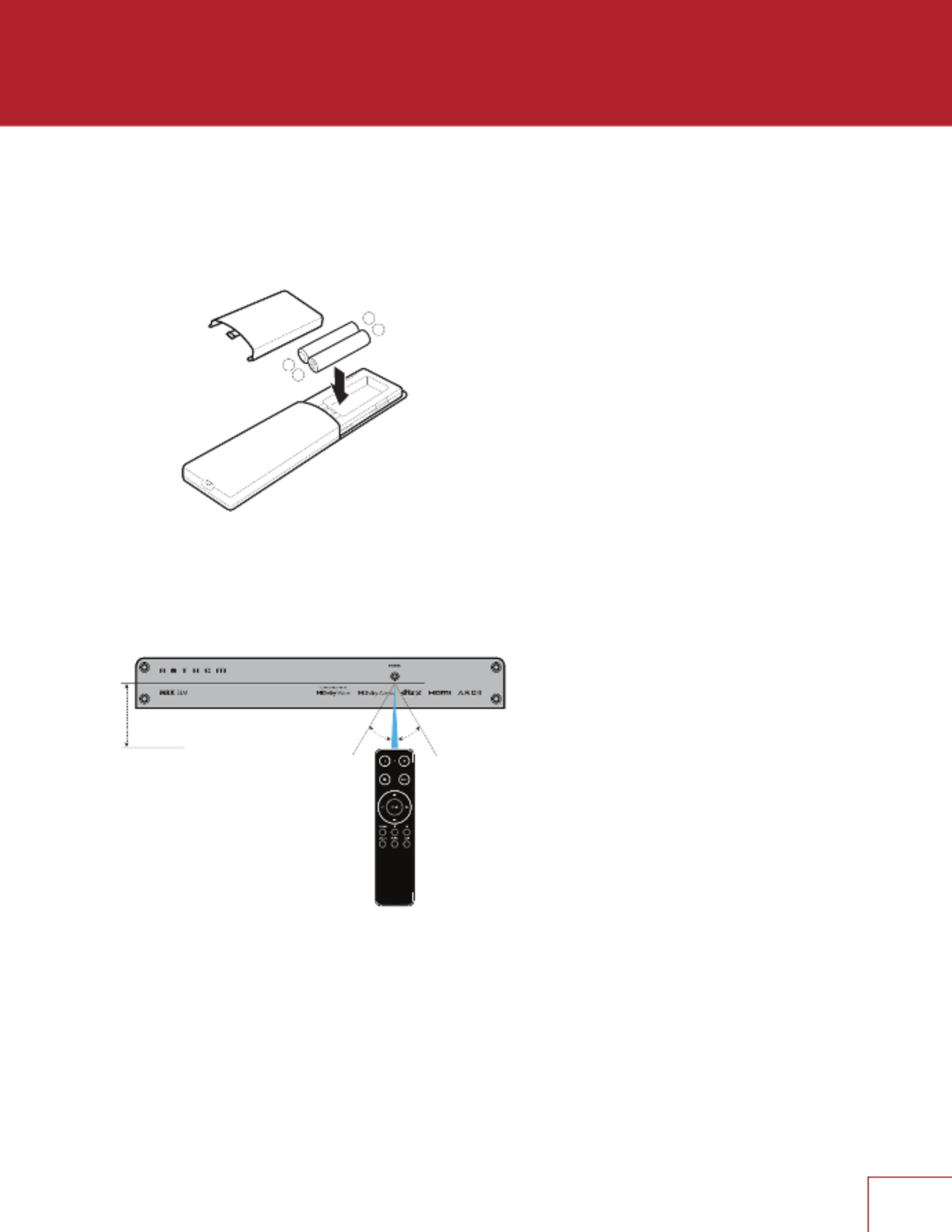
REMOTE CONTROL BATTERY INSTALLATION
Install two AAA alkaline batteries in the MRX SLM remote control in the directions shown in the
illustration below. When replacing batteries, always replace both of them with fresh batteries and
use high quality AAA alkaline type. If not using the remote for an extended length of time, remove
the batteries from the remote to avoid acid leakage that may damage the remote.
REMOTE CONTROL RANGE OF OPERATION
The MRX SLM remote control operates best when used within the range and distance shown in
the illustration below. The IR receiver is located below the Power label on the front panel.
If the unit is not facing the listening position (for example, if the unit is mounted behind a TV or in
wall), the external IR receiver (included with the accessories) can be used and mounted to face
the listening position. Peel o the double-sided tape to ax the external IR receiver in place.
REAR AND FRONT IR INPUTS
If your remote control is not working and you have already checked the batteries, before
contacting technical support, check that IR is set to “Front IR” if using the front panel IR or set to
“Rear IR” if using the external IR extender in the Network / Control menu.
ANTHEM REMOTE CONTROL APP
A remote control app is available for free to iOS and Android users. To use this app, download it
from the Google Play or Apple App Store, connect your MRX SLM to the same network as your
iOS/Android device, and launch the app.
+
–
+
–
Within
6m (20ft)
30˚ 30˚

5
MOUNTING
Before connecting cables to the MRX SLM, you should nd a good spot for it in your
entertainment system. Thanks to its small foot print and versatility, the unit can be mounted
several ways:
1. In a cabinet by adding stick-on rubber feet under the MRX SLM (included in the accessories
package).
2. Attached to the back of your TV, on the wall or inside a wall cabinet located between 2 studs,
by making use of the universal mounting bracket (included in the accessories package).
Install the mounting bracket rst and then simply snap-in the MRX SLM in place.
3. In a 19-inch rack using the rackmount kit (available as an option). Remove the 4 screws at
the front using a Torx T10 screwdriver and attach the rack mount plate by re-using the same
screws.

6
1.5 SPEAKER POSITIONING
Your MRX SLM allows connection of up to six channels (5 speakers, 1 subwoofer). When
setting up your speakers, care should be taken to achieve the best possible immersive audio
experience. The factory defaults to a 5.1 speaker conguration: fronts/center/surrounds and
subwoofer. The surround channels can be congured in the setup menu for a number of other
conguration. Please read the setup section to take full advantage of all the features.
FRONT LEFT & RIGHT
The front speakers are what you hear when listening to 2 channel recordings but also play a large
part in your home theater setup along with the centre channel playing the majority of content.
CENTER
The center channel is the most important speaker in a home theater system, as it reproduces
almost all of the dialogue, and a large portion of the front speaker information.
SURROUND LEFT & RIGHT
Surround speakers reproduce the information that makes sounds wrap around your home
theater space.
SUBWOOFER
With any surround sound system, you will need one or more high-quality subwoofers (the .1 in
5.1- or 3.1.2-channel surround systems). Most movie soundtracks contain large amounts of
bass information as part of the LFE (Low Frequency Eect) track that sends information directly
to your subwoofer. Good subwoofers will provide a foundation for the rest of the system, and
add “weight” to movies and music.
HEIGHTS
Up to two height speakers (the .2 and in 3.1.2-channel surround systems) can be connected
to allow 3-dimensional Dolby Atmos and DTS:X surround sound. Height speakers reproduce
the information that makes it sound as if planes are ying over your head and other similar
eects.
Note that as the MRX SLM has only 5 speaker outputs, you need to select to either have
surrounds or heights speakers.

7
1.6 5.1-CHANNEL SPEAKER POSITIONING
This illustration shows the recommended speaker placement for a 5.1 setup.
5.1 Conguration

8
2.1.2 Conguration
with one pair in-ceiling height speakers
3.1.2 Conguration
with one pair in-ceiling height speakers
1.7 2.1.2 and 3.1.2-CHANNEL SPEAKER POSITIONING
These illustrations show some possible speaker placements when using the surround
channels as heights.
.

9
1.8 HEIGHT EFFECTS SPEAKER POSITIONING
This illustration shows recommended speaker placement when using middle channel height eects.
One pair in-ceiling height speakers (side view)
10
This section describes connections between system components. Conguration of input
and output will be discussed later, in section 3.
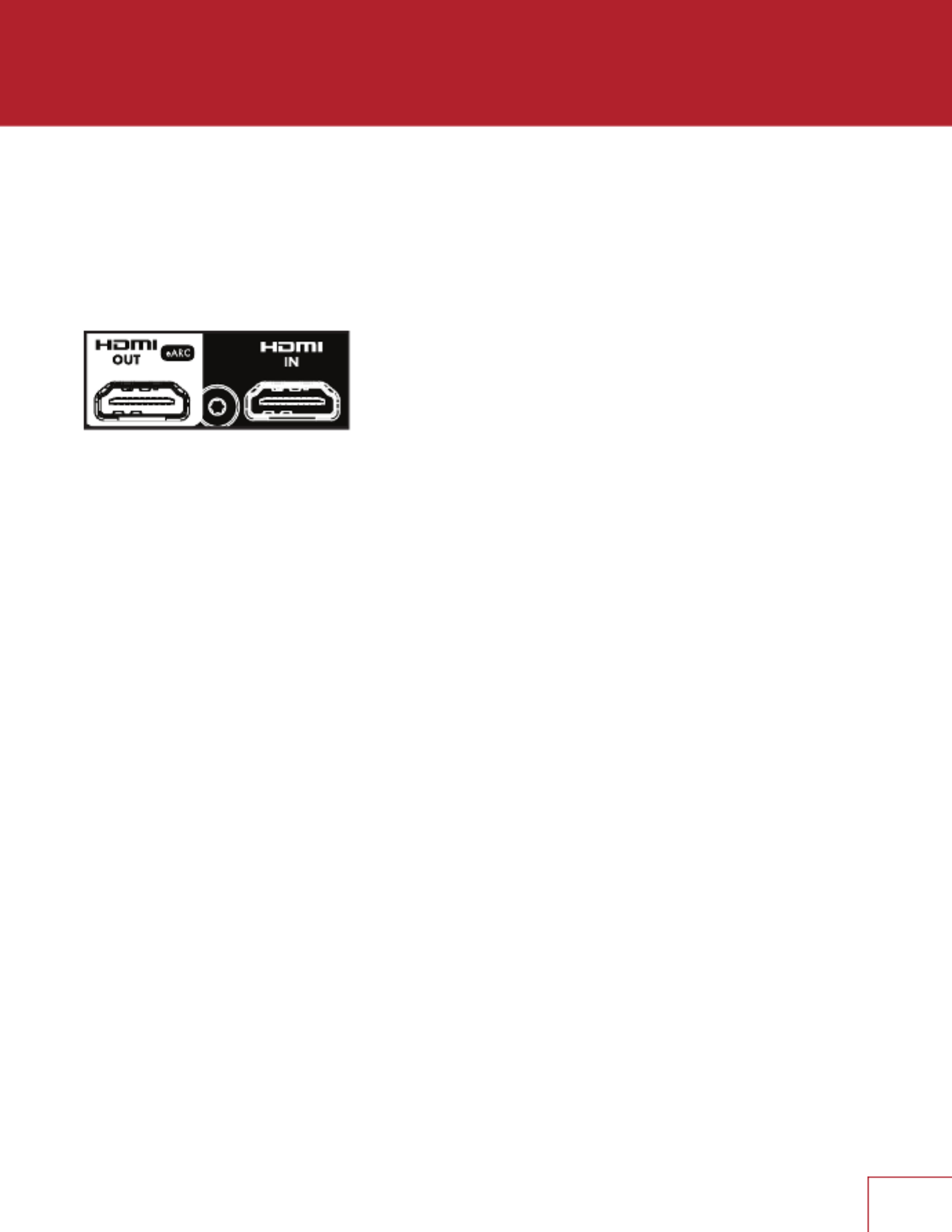
2.1 HDMI VIDEO INPUT AND OUTPUT
An HDMI connection carries video and audio signals together. Connect the HDMI output
from the MRX to a display with a HDMI input – one with the appropriate version of High-
bandwidth Digital Content Protection (HDCP) is required to display copy-protected material.
Insert HDMI cables gently, as the connector is more delicate than traditional ones.
Damaged cables can damage jacks, and the warranty does not cover jack replacement.
Therefore, replacing HDMI cables is recommended if there is any chance of damage
with the existing cable.
Use only certied High-Speed cables and connecting devices. Cables and connecting
devices that worked in an older setup may not necessarily be compatible with
newer video formats such as Deep Color, UHD, or high frame rates. If you are using
adapters or port savers, start troubleshooting by eliminating them since they can aect
bandwidth.
C O N N E C T I O N S

11
2.2 AUDIO CONNECTIONS
HDMI AND OPTICAL DIGITAL AUDIO
Digital audio sources can be connected using an HDMI or optical cable. These
connections can carry either linear PCM or bitstream (Dolby Digital, and DTS audio
formats). An HDMI connection is generally preferred to ensure the use of lossless audio
when sources provide it, although you can also use an optical connection for sources
outputting 2-channel PCM, Dolby Digital 5.1, and DTS 5.1 without aecting audio
quality.
HDMI ARC AND eARC AUDIO RETURN CHANNEL
If your television provides audio through HDMI ARC (Audio Return Channel) or eARC
(Enhanced Audio Return Channel), for example, when it accesses streaming media
sources, it can send the audio to the MRX SLM, eliminating the need for a separate
audio connection from the television.
If using eARC, ensure that the HDMI cable connecting the TV to the MRX SLM supports
eARC and that CEC is turned ON on both the TV and MRX SLM. Beware that the MRX
SLM CEC control is turned OFF by default. You may also need to change the settings
on your TV to select HDMI eARC or HDMI ARC for the audio output and set the digital
output format to bitstream audio or pass through.
ANALOG AUDIO
If a digital output is not available from your source or if an additional source is desirable,
the 3.5 mm (1/8") analog audio jack can be used as another source.
If HDMI audio from a Dolby Digital, DTS, or 2-channel PCM source is problematic,
or takes too long to switch, we recommend the use of an optical or analog audio
connection (you can still use HDMI for video). Older cable and satellite devices often
benet from this.

12
CONNECTING SUBWOOFERS
Although subwoofers are considered to be a speaker channel, they are generally self-
amplied, and thus, connect in the same way you’d connect an external amplier. Your
MRX SLM features one subwoofer output.
SPEAKER CONNECTIONS
Remove the Euroblock connector by gently pulling away until it releases. Use a small
slotted screwdriver to loosen and tighten each contact on the Euroblock when inserting
the speaker wire (up to 12 AWG / 4mm2).
Identify which speaker wires connect to Front left/right, Surround left/right and Center
speakers.
Connect the red (+) connection of the speaker to the positive (+) contact on the
Euroblock connector, as indicated by the printing located on the SLM (above the
connector) and on the connector itself. Connect the black (–) connection of the speaker
to the negative (–) contact on the Euroblock connector as indicated by the printing
located on the MRX SLM (above the connector) and on the connector itself.
Do not connect more than one speaker to each speaker output on the Euroblock
connector. Be sure to turn o the power when connecting or disconnecting anything.
Only use speakers rated for use with the MRX SLM.
14
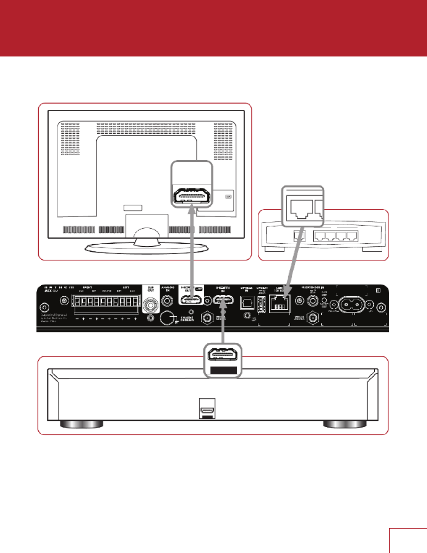
TYPICAL CONNECTION
WA
1 2 3 4
LAN
HDMI OUT
HDMI I N
1
HDMI IN
(eARC)
HDMI OUT

15
The MRX SLM does not have a traditional front panel with volume knob and display but can be
controlled using a traditional IR remote control, Anthem Remote App (iOS and Android available),
web interface, via some custom home automation equipment (such as Crestron or Control4) and
even other applications such as Spotify or Google Home. The unit can be controlled by all these
control devices at the same time. For example, you can use the Spotify app to select your favorite
play list and adjust the volume, but you can then use the MRX SLM remote to skip a track or the
Anthem Remote App to change the listening mode.
3.1 NETWORK SETUP
If you intend to only use the IR remote and streaming only via Bluetooth, no network connection is
required. BUT you will need one to run the Anthem Remote App, access the setup parameters, do
an Anthem Room Correction, installing software updates or streaming audio from the internet.
You can connect to your network several ways:
1. Ethernet/LAN Connection: The simplest way to connect your MRX SLM to your network is
by connecting it via an Ethernet cable to the LAN 10/100 port at the back of the MRX SLM.
This will provide the quickest setup, most secure and most reliable network connection.
2. Wi-Fi Conguration via Apple® iOS:
a. Enter your iOS device Wi-Fi Settings Menu.
b. Locate your MRX SLM under “Set up new AirPlay speaker.” The MRX SLM will be shown
as “MRX SLM-xxxxxx” in the list of available devices (where xxxxxx represents the last few
characters of the LAN MAC ID, as shown at the back of the unit)
c. Select your MRX SLM unit and follow the instructions to connect it to your network.
3. Wi-Fi Conguration via Android:
a. Download the Google Home application from the Play Store and launch it.
b. You should be prompted that there is a device available for setup. Follow the instructions
to add it to the network. If not, tap “+” followed by “Setup a Device” and follow the
instructions on screen. The MRX SLM will be shown as “MRX SLM-xxxxxx” in the list of
available devices (where xxxxxx represents the last few characters of the LAN MAC ID, as
shown at the back of the unit).
NOTE: If you connect to your network before connecting speakers, you will obviously not hear the
connection chime.
4. Wi-Fi Conguration via setup menu:
a. Connect the MRX SLM to your network using a wired Ethernet/LAN cable.
b. Setup a wireless connection by following the instructions shown in the SYSTEM SETUP –
WI-FI CONFIGURATION.
c. Disconnect the Ethernet/LAN cable. The unit will then connect to the wireless network
automatically.
O P E R A T I O N

16
3.2 ANTHEM REMOTE APP OPERATION
The Anthem Remote App gives you full control of your MRX SLM and can be downloaded for free
from the Apple or Google stores by looking it up using the keywords “Anthem remote”.
When starting the app, the welcome screen will show you available devices on the network. Select
the MRX SLM will then show a screen with basic control such as volume and source/listening
mode selection. Settings will give you access to the tone controls and various speakers level
adjustments. Setup Menu will give you access to various system conguration settings.
More details about the setup that can be done via the app UI can be found in the SETUP (WEBUI
& MOBILE UI) section.
3.3 WEB USER INTERFACE OPERATION
Controlling the MRX SLM can also be done using a browser on a device connected to the same
network such as a phone, tablet or computer. The web interface lets you access the basic control
as well as all system settings.
To access the MRX SLM web user interface, you will rst need to identify the IP address of the
MRX SLM. This can be found various ways, but the easiest are as follow:
Using the Anthem Remote App: When starting the app, the IP address of the unit will be shown
in the opening screen. If the main screen is shown, simply click on “Discovery” to return back to
the opening screen. Once you know the IP address of the unit, you can use a browser such as
Safari or Google Chrome to access the web interface by typing the IP address into the URL bar.
Using File Explorer: If using a Windows PC, start File Explorer and click on “Network”. The MRX
SLM will be shown under Media Devices. Double-clicking on the MRX SLM icon will open your
web browser and will access the unit. The IP address will be shown in the URL bar that can be
use in the future.
Using a network scanner: You can use a network scanner such as Fing or Angry IP to discover
the MRX SLM IP address.
More details about the setup that can be done via the web UI can be found in the SETUP (WEBUI
& MOBILE UI) section.

17
3.4 TRADITIONAL REMOTE CONTROL OPERATION
Controlling the MRX SLM can also be done using the IR remote
included in the accessory package.
1 – Power on
2 – LED - Flashes when a key is pressed. The LED stops ashing
indicates that the batteries are not inserted properly or that the
batteries are drained.
3 – Standby
4 – Mute
5 – Listening Mode
6 – Navigation Controls - The left/right buttons select the
previous/next track. The center button acts as a Play/Pause
button. The up/down buttons control the volume.
Input Source Selection
7 – Stream
8 – Bluetooth
9 – TV (ARC or eARC)
10 – Analog
11 – Digital (Optical)
12 – HDMI
13
4
6
7
10 11
9
5
8
2
12

19
3.4.3 INPUT SELECTION
The number of active inputs varies according to how the Input Setup menu was programmed. By
default, 6 inputs are dened and are mapped to the source keys on the remote. If more inputs are
dened (up to 30 virtual inputs can be dened) pressing the source key another time will switch to
the next virtual input using the physical connector. If a connector is used for more than one virtual
input, pressing the remote source button another time will select the next virtual input which also
makes use of this connector (and will eventually cycle around to the rst one). If switching from a
dierent source, the rst virtual input making use of this connector will be selected.
For example, if you have dened a virtual input labeled “TV-late” (using the HDMI connector
eARC/ARC for audio input and a speaker prole without a subwoofer), pressing the TV button the
rst time will be using the default TV input, but pressing it a second time will be using TV-late. If
selecting another input (such as Digital), and then selecting TV will revert to the rst input attached
to your TV.
The STREAM input is automatically selected when starting the audio from your player, whether
you are streaming via AirPlay, Chromecast or using an application such as Spotify. If the unit is in
standby, it will turn on automatically.
The Bluetooth input (shown on the remote with the Bluetooth logo) works similarly, but pairing your
device with the MRX SLM needs to be done once. Refer to the “Streaming via Bluetooth” section
below for details.
When dening multiple virtual inputs, using the Anthem Remote App or the web interface is
recommended for ease of use.

20
The MRX SLM factory defaults for the 6 inputs are congured as follow:
SOURCE AUDIO INPUT VIDEO INPUT
HDMI HDMI HDMI
TV (ARC/eARC) TV (ARC/eARC) None
Streaming Streaming None
Bluetooth Bluetooth None
Digital (Optical) Optical None
Analog Analog None
The virtual inputs that give you complete control of the name of each input you create, along with whether
video (HDMI) will be used, which audio input (HDMI, digital, analog, streaming, or Bluetooth) to use, which
speaker prole to use, and much more. For information on setting up inputs, refer to the Setup section of
this manual.

21
3.5 STREAMING VIA AirPlay®
To listen to audio via AirPlay on your MRX, ensure your Apple device is connected to the same
network as the MRX SLM and simply select it as the AirPlay audio playback device.
Note: The MRX will appear as the device name dened in the General Settings in the AirPlay
speaker menu. The factory default for the MRX SLM name is “MRX SLM-xxxxxx” (where xxxxxx
represents the last few characters of the LAN MAC ID, as shown at the back of the unit).
3.6 STREAMING VIA CHROMECAST BUILT-IN
1. To listen to Cast audio from any supported application on your MRX SLM, ensure your device
is connected to the same network as the MRX SLM via either a wired or wireless connection.
Chromecast will also only work if the MRX SLM has been congured as a device using the
Google Home app.
2. Tap the Cast icon from within the application and select the MRX SLM as the playback device.
The factory default for the MRX SLM name is “MRX SLM-xxxxxx” (where xxxx represents the
last few characters of the LAN MAC ID, as shown at the back of the unit).
STREAMING VIA SPOTIFY CONNECT
Use your phone, tablet or computer as a remote control for Spotify. Go to spotify.com/connect to
learn how.

22
3.7 STREAMING VIA BLUETOOTH
Bluetooth connection requires both wireless antennas to be attached to the SLM and requires your
device to rst be paired. Select the Bluetooth input to enter pairing mode to enter pairing mode
(the front panel power LED will ash blue). The front LED of the MRX SLM will start double-ashing
indicating that pairing is in progress. Access the Bluetooth pairing screen on your device to select
the MRX SLM and initiate the connection. Once the link is established, the front LED will turn back
solid blue. The MRX SLM shown in the available Bluetooth devices will be advertise as the device
name dened in the General Settings.
The factory default for the MRX SLM name is “MRX SLM-xxxxxx” (where xxxxxx represents the
last few characters of the LAN MAC ID, as shown at the back of the unit). This pairing process
need only to be done once.
Once paired, streaming audio via Bluetooth works the same as streaming using other method
such as AirPlay or Chromecast. On your device, select the MRX SLM as the BT audio playback
device and start streaming to it. The MRX SLM will automatically switch to the Bluetooth input and
will even turn on if in standby.

23
Controlling and accessing setup parameters of the MRX SLM can be done using a browser
on a device connected to the same network such as a phone, tablet or computer. To access
the MRX SLM web user interface, you will rst need to identify the IP address of the MRX
SLM. Refer to the OPERATION section for details.
The Anthem Remote App can also be used to access the mobile UI. The app does not need
any IP address and will discover the MRX SLM on your network. Setup can be done by
clicking on Settings and then accessing the Setup Menu.
4.1 INFORMATION PAGE
WEBUI info page is accessed by clicking on the icon of the MRX SLM from the left
toolbar, this page is used for viewing information about your MRX SLM’s hardware and
software versions as well as network and system status. No information can be changed
here, just viewed.
MOBILE UI info page is accessed by clicking on the Anthem logo on the top left corner of
the Setup Menu screen. This page is used for viewing basic information about your MRX
SLM’s and app software versions. No information can be changed here, just viewed.
Information
Information
Network Module
System Status
INFORMATION
View general information about your MRX SLM, including rmware versions and serial
number.
NETWORK MODULE
View all network related information.
SYSTEM STATUS
View all information related to incoming audio and video signals. Note that this section
displays what is being sent as a description, and can be potentially incorrect.
4.2 QUICK ACCESS
Quick access to the volume, source selection, listening mode, tone control and speaker
trims are shown in a single page for the web UI. The Anthem Remote App splits this
in 2 screens: the tone control and speaker trims are accessed by clicking on Settings.
Access to the Setup Menu via the app is also done by clicking on Settings.
S E T U P ( W E B U I A N D M O B I L E U I )

24
MAIN ZONE
Quick Access
Audio
Levels
Streaming Input Transport (WEBUI only)
AUDIO
Control the basics of your MRX SLM from this page. Power On/O, change volume and
inputs from here.
LEVELS
Set levels for individual speakers, as well and/or tone controls such as Balance,
Treble and Bass.
STREAMING INPUT TRANSPORT (WEBUI ONLY)
Control playback when Streaming input is active. Allows for various playback modes
(normal, shue, repeat, etc), and transport controls. This option will only appear in the
Main Zone window when the current input is set to Streaming.
4.3 SYSTEM SETUP – GENERAL SETUP
System Setup
General Settings
Power Saving
Main Zone
CEC Settings
GENERAL SETTINGS
System Setup
Device Name
Language
Distinct Units
Master Volume Scale
Standby HDMI Bypass

25
DEVICE NAME
Allows you to change the name of the unit. This will also help to identify units in ARC and
dierent streaming platforms. The factory default for the MRX SLM name is “MRX SLM-
xxxxxx” (where xxxxxx represents the last few characters of the LAN MAC ID, as shown at
the back of the unit).
LANGUAGE
Set the language you would like the menu to appear in.
DISTANCE UNITS
Choose between imperial and metric versions of measurement.
MASTER VOLUME SCALE
By default, this is set to “dB” which is common for most modern receivers. “dB” references
the volume trim of the incoming signal where “0.0 dB” is the unaltered signal coming in from
a source. While this is the standard, it can be confusing for new users. “%” oers a volume
scale of 0-100, which is standard for computers, televisions and most sources.
STANDBY HDMI BYPASS
Passes the HDMI input directly to the display while the unit is in Standby mode.
POWER SAVING
System Setup
No Signal Power O
NO SIGNAL POWER OFF
When there is no input signal, the MRX SLM turns o after the selected time: 5, 10, or 20
minutes, 1, 2, or 6 hours, or “Never.” The default setting is 20 minutes.
MAIN ZONE
System Setup
Power-On Volume
Maximum Volume
Power-On Input

26
POWER-ON VOLUME
This setting controls the volume level to use when powering on the MRX SLM from standby
mode. To power-on at the last used volume, select “Last Used” by changing the value to
less than -90.
MAXIMUM VOLUME
This setting allows you to limit the maximum volume output of the MRX SLM to avoid
damaging equipment or hearing.
POWER-ON INPUT
This setting controls which input to use when rst powering on the MRX SLM. Select from
one of the available inputs or “Last Used.”
CEC SETTINGS
System Setup
CEC Control
CEC Power-O Control
HDMI Audio to TV
CEC CONTROL
With CEC enabled, Consumer Electronics Control (CEC) allows controlling an HDMI-
connected component using another brand’s remote control (as long as the other
components have CEC enabled). Note that when components are from dierent brands, this
control system may not be reliable.
CEC Control should be enabled if eARC is utilized. Note that CEC Control is disabled by
default and that reloading factory defaults will turn it o.
With CEC, turning on (or o) one component in the system can turn on (or o) the rest of the
system. You may or may not want this, which is why we provide separate options for CEC
Power O Control. When either setting is disabled, the MRX SLM ignores corresponding
power O commands sent by other HDMI-connected components.
CEC POWER-OFF CONTROL
Allows connected devices to set the MRX SLM in standby mode.
HDMI AUDIO TO TV
This option allows audio from the HDMI source to be sent to the TV in addition to be
extracted by the MRX SLM. By default, it is turned o, so no audio can be heard from the TV.

27
4.4 SYSTEM SETUP – SPEAKERS SETUP
System Setup
Channel Mapping
Speaker Proles
Speakers On / O
Speaker Distances
Speaker Levels
Subwoofer
Crossovers
CHANNEL MAPPING
System Setup
Amp Matrixing
AMP MATRIXING
Amp matrixing is where you assign the surround channels to their desired function.
1. Select amp matrixing for surround speakers for a standard 5.1 speaker conguration.
2. Select Front (Bi-Amp) to use the surround channels to drive your fronts L/R speakers in
bi-amp mode.
3. Select any of the other speaker conguration (e.g. Front In-Ceiling or Front Dolby) if using
a 3.1.2 speaker conguration.
When the surround channels have been re-mapped to a dierent channel, the name of the
actual channel will be shown. For example, if Dolby Front has been selected for the surround
output, when setting the distance, level or crossover the label “Surround” will be replaced by
“Front Dolby” in the user interface. For ease of readability, the manual refers to Surround in
the Speakers Setup section.
Note that the function of the surround channels applies to all 4 channel proles.
SPEAKER PROFILES (1-4)
The use of one speaker prole is suitable for most systems. However, the MRX SLM allows
up to four unique proles with unique speaker selections, bass management, listening
position, level calibration, and Anthem Room Correction (ARC) equalization values. Multiple
speaker proles are useful if your listening room varies according to predictable sound-
altering characteristics such as screen up versus down, a door open versus closed, or
stereo listening for music vs. home theatre.

28
System Setup
Prole Name
Calibration Level
Test Noise
PROFILE NAME
Each prole can be renamed, with up to 64 ASCII characters, fewer if other-language letters
with accents are used.
CALIBRATION LEVEL
This setting adjusts the volume for this menu’s test noises. It changes the output of all
channels.
TEST NOISE
To play the test noise, use the pull-down menu to select the desired channel or None to
turn it o. While the test noise is playing, you can balance the level of individual channel by
adjusting them in the Levels (see below).
SPEAKERS ON / OFF
System Setup
Subwoofer / Center / Surround
SUBWOOFER / CENTER / SURROUND
Activate output to the speakers, note that the Front Left/Right cannot be turned o. The
subwoofer output will not function unless it has been indicated that a subwoofer is present. If
using a subwoofer, this should be enabled prior to running ARC.
SPEAKER DISTANCES
System Setup
Subwoofer / Front Left / Front Right / Center / Surround Left / Surround Right
SUBWOOFER / FRONT LEFT / FRONT RIGHT / CENTER / SURROUND LEFT / SURROUND
RIGHT
Adjust the distance from the primary listener position to individual speakers. If running ARC,
let it set the distances for you.

29
SPEAKER LEVELS
System Setup
Subwoofer / Front Left / Front Right / Center / Surround Left / Surround Right
SUBWOOFER / FRONT LEFT / FRONT RIGHT / CENTER / SURROUND LEFT / SURROUND
RIGHT
If you’re calibrating by ear, use the webUI, and sit in the listening area. Adjust each channel’s
loudness until all levels sound the same. If using an SPL meter, adjust the level until it reads
75 dB for each channel. If Front Left was at 0dB when you set Calibration Level, then no
adjustment of Front Left is necessary. If using a powered subwoofer, adjust the sub’s built-in
level control before setting the subwoofer level in this menu or using ARC. Speakers set to
“O” in the Bass Management menu can not be adjusted. Note that if ARC has been used
to set levels and is then turned o, the subwoofer level should be reduced by the same
amount as room gain, or else you’ll hear elevated subwoofer output.
SUBWOOFER
System Setup
Phase Frequency
Phase
Polarity
PHASE FREQUENCY
Phase Frequency allows you to select at which frequency the phase shift is applied (generally
the same frequency as the crossover).
PHASE
Adjusts the phase of the subwoofer relative to the main channels. Phase is adjustable from
0-180 degrees. If a value higher than 180 degrees is required, adjust Subwoofer Phase in
combination with Sub Polarity for a full 360-degree range of adjustment. When using ARC,
this value is automatically set using the Automatic Phase Adjustment tool.
POLARITY
Adjusts the polarity of the subwoofer to either 0 or 180 degrees. When selecting 180
degrees, the subwoofer signal is inverted when compared to the main channels. As a
general guide, set Phase and Polarity to 0 if the subwoofer is near the front speakers and set
Phase to 0 and Polarity to 180 if the subwoofer is near the back of the room. When using
ARC, this value is automatically set using the Automatic Phase Adjustment tool.

30
CROSSOVERS
System Setup
LFE Low Pass Filter
Front, Center and Surround Crossover
LFE LOW PASS FILTER
Sets the Low Pass Filter (LPF) frequency for Low Frequency Eects (LFE).
FRONT, CENTER AND SURROUND CROSSOVER
Sets the crossover point between the subwoofer channel and the selected speaker(s). This
value will be set by ARC. If the crossover value changes to a number other than the default
selected by ARC, you must modify the crossover setting in ARC and recalculate and upload.
These crossover values should only be adjusted if ARC has not and will not be run.
4.5 SYSTEM SETUP – INPUTS SETUP
The MRX SLM has by default 6 inputs but up to 30 virtual inputs can be dened. This allows
you to quickly change a number of parameters by simply selecting an input. For example,
you may want to create a late night listening mode by selecting a speaker prole with no
subwoofer and Dolby Audio Post-Processing set to Night mode.
System Setup
Insert Before Input
Add Input
Delete Input
Input Name
Video Input
Audio Input
Speaker Prole
Mode Presets
Anthem Room Correction
Dolby Audio Post-Processing
Dolby Speaker Virtualization
Dolby Dynamic Range Control
Lip Sync
Input Trim
INSERT BEFORE INPUT
Create a new input, and specify its location within the input list.
ADD INPUT
To add a new input at the end of the list, highlight and press “Add Input”.

31
DELETE INPUT
To delete an input, click on the X on the top right corner and click on OK to conrm. Note
that the currently selected input CANNOT be deleted.
INPUT NAME
Each input can be renamed, with up to 64 ASCII characters, fewer if other-language letters
are used.
VIDEO INPUT
Select whether HDMI video will be enabled or not.
AUDIO INPUT
Select the connection to use: HDMI, TV (ARC/eARC), Streaming, Bluetooth, Digital (Optical),
Analog or None.
SPEAKER PROFILE
Select the prole to use with this input. This is where you can select previously made
speaker proles for dierent situations, such as 5.1 vs. 2 channel.
AUDIO MODE PRESETS
A listening mode is processing that enhances source material by increasing the number of
output channels. Each available mode performs this dierently, providing a unique type of
sound. To nd your preference, spend some time listening to various modes using various
sources. To disable presets and make selections entirely on the y, select “Last Used.” To
disable listening modes altogether, select “None.”
System Setup
AnthemLogic – Cinema
AnthemLogic – Music
Dolby Surround
DTS Neural:X
DTS® Virtual:X™
All Channel Stereo
Mono
All Channel Mono
ANTHEMLOGIC – CINEMA
AnthemLogic-Cinema lets you experience full impact home theater sound from any
2-channel source. This mode creates an extensive, enveloping, and dynamic listening
experience, making 2-channel movies sound more like a state-of-the-art movie theatre.
Through extensive listening tests, Anthem engineers developed this proprietary mode
avoiding the use of echo eects, which could negatively aect the purity of the sound.

32
ANTHEMLOGIC – MUSIC
AnthemLogic-Music enhances the stereo listening experience without detracting from the
stereo soundstage. This mode is also a minimalist design that uses no echo or reverberation
eects. To ensure that the purity of the stereo music soundstage is not compromised when
you’re sitting in the “sweet spot” listening to your favorite stereo recordings, this mode uses
no center channel.
DOLBY SURROUND
Dolby Surround up-mixes all stereo, 5.1, and 7.1-channel content to take full advantage of all
speakers in a Dolby Atmos system. Unlike previous wideband upmixing technologies, Dolby
Surround can steer frequency bands individually, producing surround sound with precisely
located audio elements and a spacious ambiance. Dolby Surround replaces the Dolby Pro
Logic II family of upmixers, oering greater exibility and superior audio performance.
DTS® VIRTUAL:X™
DTS® Virtual:X™ Technology delivers an enhanced sound immersion and home theater
experience with as few as two speakers. This transforms your movies, music, or games
to deliver life-like sound above, beside, and behind you. Designed to perform in any room
regardless of size, layout, or acoustics, DTS® Virtual:X™ technology is a exible, virtual audio
solution for any room conguration or budget. It is also an ideal companion for DTS:X
®
immersive decoders or any other immersive TV audio decoder.
ALL CHANNEL STEREO
All Channel Stereo mode sends the left and right channels to the surround channels with
equal loudness while the center channel and subwoofer receive a combination of both.
MONO
MONO sums all the channels and sends it to the center channel. All other channels are
muted.
ALL CHANNEL MONO
All Channel Mono sums all channels and distributes an identical signal across all speakers.
The only dierence between each signal speaker will be determined by their crossover
setting and therefore how much bass each will play.
ANTHEM ROOM CORRECTION
The ARC measurement process, described later, automatically turns this On. To disable
room equalization afterward, change this to “O.” If room correction isn’t loaded, “N/A” is
displayed.
DOLBY AUDIO POST-PROCESSING
Select “Music”, “Movie”, “Night” or “None.” Dolby Volume makes content with signicant
dierences in volume easy to listen to by analyzing it and intelligently adjusting two things—
level and frequency response. It does this continually without causing pumping and
breathing artifacts that are common with traditional dynamic range compressors. In doing
so, the volume setting is taken into account, as is our hearing’s declining sensitivity to the
lowest and highest frequencies relative to the midrange as their levels drop. The result is
that the perceived frequency response remains constant while making quieter parts of the
content more listenable.

33
DOLBY SPEAKER VIRTUALIZATION
Enable Dolby Atmos Height Virtualization to create the sensation of overhead sound
from the listener-level speakers. For stereo and 3.1-channel speaker conguration, Dolby
Atmos height virtualization is combined with surround virtualization to create an enveloping
360-degree audio minus the speakers that would ordinarily be employed behind or to the
side of the listener.
DOLBY DYNAMIC RANGE CONTROL
When disabled, the signals are played back at the original volume: quiet signals remain
quiet and loud signals remain loud. Enabling DDR compresses the volume dierence and
increases the overall volume. The audio is easier to hear, regardless of the dynamic range
of the sound source. When set to Automatic, the encoding of the input signal is used to
determine which processing to use.
LIP SYNC
If you hear the audio before seeing its corresponding image, you can set up to ve hundred
(500) milliseconds of audio delay. Set this using trial and error or, a synchronization test
disc. Movies are not always the best test because sounds, including dialog, are usually re-
recorded after the lming is completed, and can be slightly out of sync at various points in
the recording.
INPUT TRIM
If your inputs have varying degrees of volume output, you can normalize them by setting your
input trim per input. This oers both + and - options for input trim, but it is recommended to
set your quietest input at 0.0 dB and normalize your louder ones around that by trimming
them down.
4.6 SYSTEM SETUP – NETWORK SETUP
System Setup
Network / Control
IP Status
Ethernet Conguration
Wi-Fi Conguration
NETWORK / CONTROL
System Setup
TCP Port
IR

34
TCP PORT
Allows you to change the TCP Port number. Only values between 1025 and 49150 are
accepted. Note that this should only be changed if there is a conict on the network with
another component.
IR
Select whether the IR signal from the remote control is decoded using the Front IR receiver
or the Rear IR jack. When selecting Rear IR, make sure to connect the IR extender cable
(included in the accessories) in the jack labeled IR EXTENDER IN located beside the AC inlet.
IP STATUS
Displays the status of the current network connection, IP mode, IP address as well as the
subnet, gateway and DNS.
ETHERNET CONFIGURATION
Settings in this submenu should only be changed if you want to use a static IP address and
want to dene the subnet, gateway and DNS. You can always revert back to Auto (DHCP)
mode by holding the DHCP Reset button (located beside the AC inlet) for more than 2
seconds (but less than 5).
*No changes will take eect until the “Apply” button is clicked.
WI-FI CONFIGURATION
Settings in this submenu lets you connect to a wireless network manually. Click on Scan
to start populating the available networks that will be shown in the SSID pull-down. Type in
the Password and click on Apply to congure the MRX SLM. Once the LAN cable will be
disconnected, the unit will connect to the wireless network automatically.
If you don’t have a LAN cable, you can setup the wireless network by using the Google
Home application or via AirPlay. Refer to the OPERATION section for details on how to
do this.
*No changes will take eect until the “Apply” button is clicked.
4.7 SYSTEM SETUP – STORE / LOAD / UPDATE
System Setup
Store / Load Settings
Export / Import Settings
Firmware Update
36
EXPORT SETTINGS
Creates a le that can be saved on your PC allowing you to copy settings to another MRX
SLM or in the event of a replacement unit or service, this le can be used to reload the
settings.
IMPORT SETTINGS
Allows you to upload a le of settings that you have previously created either from this unit or
another MRX SLM.
FIRMWARE UPDATE
Firmware updates (whether beta or fully-released versions) will preserve your settings and
ARC parameters.
System Setup
Beta Updates
Check for Update
BETA UPDATES
When selected, your MRX SLM will become enrolled in our beta over-the-air receiver update
program that provides updates to help with testing new software, which will either include
bug xes or new features.
Note that beta updates are not necessarily ready for full release and may introduce new
bugs into your MRX SLM (which can be resolved by reverting to the old software or waiting
for the newer version of the beta software) if you are not comfortable with potential bugs,
leave this setting at its default position. A check for a beta update is automatically performed
once a day. This option requires an internet connection.
CHECK FOR UPDATE
When you select this option, it will scan for a software update and prompt to update if one is
found. Note that the newest software will be selected; if you have “Beta Updates” enabled,
this le can be a beta or full release rmware version. This option requires an internet
connection.
Produkspesifikasjoner
| Merke: | Anthem |
| Kategori: | Mottaker |
| Modell: | MRX SLM |
Trenger du hjelp?
Hvis du trenger hjelp med Anthem MRX SLM still et spørsmål nedenfor, og andre brukere vil svare deg
Mottaker Anthem Manualer

15 Januar 2025
Mottaker Manualer
- Mottaker Bosch
- Mottaker Power Dynamics
- Mottaker Vonyx
- Mottaker Akg
- Mottaker Jensen
- Mottaker Hartke
- Mottaker Philips
- Mottaker Goobay
- Mottaker Godox
- Mottaker Cayin
- Mottaker Meridian
- Mottaker Fender
- Mottaker Kogan
- Mottaker Sony
- Mottaker Pro-Ject
- Mottaker Yamaha
- Mottaker Morel
- Mottaker Extron
- Mottaker Lindy
- Mottaker NuPrime
- Mottaker Ecler
- Mottaker AudioControl
- Mottaker Rotel
- Mottaker Audio-Technica
- Mottaker Toa
- Mottaker Marantz
- Mottaker Rega
- Mottaker Vox
- Mottaker Pyle
- Mottaker Shure
- Mottaker Roland
- Mottaker JVC
- Mottaker VMV
- Mottaker S.M.S.L
- Mottaker Kicker
- Mottaker Auna
- Mottaker OSD Audio
- Mottaker DataVideo
- Mottaker Audizio
- Mottaker Blackstar
- Mottaker Hertz
- Mottaker Kenwood
- Mottaker Cambridge
- Mottaker MB Quart
- Mottaker Aplic
- Mottaker CSL
- Mottaker IFi Audio
- Mottaker Henry Engineering
- Mottaker Block
- Mottaker Advance
- Mottaker Artsound
- Mottaker Denon
- Mottaker Marshall
- Mottaker Yorkville
- Mottaker JBL
- Mottaker Infinity
- Mottaker Helix
- Mottaker Soundstream
- Mottaker Klipsch
- Mottaker PAC
- Mottaker Bellari
- Mottaker Rolls
- Mottaker Ground Zero
- Mottaker Karma
- Mottaker Glemm
- Mottaker EA
- Mottaker Match
- Mottaker Renkforce
- Mottaker Scansonic
- Mottaker SPL
- Mottaker Crunch
- Mottaker QSC
- Mottaker A-NeuVideo
- Mottaker Classé
- Mottaker FoneStar
- Mottaker Monitor Audio
- Mottaker Peavey
- Mottaker Crown
- Mottaker Fosi Audio
- Mottaker Graupner
- Mottaker Antelope Audio
- Mottaker Vaddio
- Mottaker ESX
- Mottaker Omnitronic
- Mottaker Russound
- Mottaker MEE Audio
- Mottaker Monacor
- Mottaker GigaBlue
- Mottaker Mx Onda
- Mottaker Black Hydra
- Mottaker Electro-Voice
- Mottaker Boss
- Mottaker JL Audio
- Mottaker Shanling
- Mottaker Atlas Sound
- Mottaker Comica
- Mottaker Ashly
- Mottaker MuxLab
- Mottaker Audiolab
- Mottaker Lectrosonics
- Mottaker Memphis Audio
- Mottaker Primare
- Mottaker Elektrobock
- Mottaker PureLink
- Mottaker Kramer
- Mottaker ATen
- Mottaker Blustream
- Mottaker Mtx Audio
- Mottaker Yaesu
- Mottaker Musical Fidelity
- Mottaker Vimar
- Mottaker Bogen
- Mottaker RDL
- Mottaker Harman Kardon
- Mottaker Dynacord
- Mottaker Ferguson
- Mottaker DAP Audio
- Mottaker REL Acoustics
- Mottaker Inovonics
- Mottaker KanexPro
- Mottaker BZBGear
- Mottaker Bresser
- Mottaker InLine
- Mottaker Ram Audio
- Mottaker Phoenix Gold
- Mottaker Strong
- Mottaker Vincent
- Mottaker HiFi ROSE
- Mottaker Intelix
- Mottaker Comprehensive
- Mottaker Deaf Bonce
- Mottaker Fiio
- Mottaker Lab Gruppen
- Mottaker GlobalSat
- Mottaker AVMATRIX
- Mottaker Imperial
- Mottaker Hifonics
- Mottaker Hotone
- Mottaker Phonic
- Mottaker AudioSource
- Mottaker Taga Harmony
- Mottaker SoundTube
- Mottaker James
- Mottaker Devialet
- Mottaker ButtKicker
- Mottaker Antelope
- Mottaker Futaba
- Mottaker Crest Audio
- Mottaker Mooer
- Mottaker Rexing
- Mottaker Marshall Electronics
- Mottaker Atoll
- Mottaker Inter-M
- Mottaker Esoteric
- Mottaker Alto
- Mottaker Konig & Meyer
- Mottaker Lumantek
- Mottaker Aguilar
- Mottaker Mark Levinson
- Mottaker Selfsat
- Mottaker Proel
- Mottaker Audibax
- Mottaker Luxman
- Mottaker Sound Ordnance
- Mottaker Wavtech
- Mottaker Parasound
- Mottaker Benchmark
- Mottaker Koda
- Mottaker Technical Pro
- Mottaker Naim
- Mottaker Audison
- Mottaker Loxjie
- Mottaker DARTS
- Mottaker ETON
- Mottaker Elipson
Nyeste Mottaker Manualer
30 Mars 2025
30 Mars 2025
30 Mars 2025
30 Mars 2025
29 Mars 2025
29 Mars 2025
29 Mars 2025
27 Mars 2025
19 Mars 2025
14 Mars 2025