Extron DTP3 CrossPoint 622 Bruksanvisning
Les nedenfor 📖 manual på norsk for Extron DTP3 CrossPoint 622 (4 sider) i kategorien Bryter. Denne guiden var nyttig for 14 personer og ble vurdert med 4.5 stjerner i gjennomsnitt av 2 brukere
Side 1/4

1
DTP3 CrossPoint Series • Setup Guide
IMPORTANT NOTE:
Go to www.extron.com for the complete user guide, installation instructions, and specications before connecting the
product to the power source.
This guide provides basic instructions for an experienced technician to install the DTP3 CrossPoint matrix switchers.
The DTP3 CrossPoint matrix switchers distribute HDCP-compliant HDMI and Extron proprietary DTP video and audio signals to any
combination of outputs simultaneously (see gure 1). The DTP3 CrossPoint inputs can be congured to accept DTP3, DTP, or XTP
signals and the DTP outputs can be congured to DTP, DTP3, XTP, or HDBaseT modes via Product Conguration Software (PCS).
The DTP3 CrossPoint switchers support 4K 60 Hz 4:4:4 signals, audio DSP Pro, and AEC and are compatible with all DTP and DTP3
transmitters and receivers. Additionally, the DTP3 CrossPoint SL models have the ShareLink Pro module for sharing content from
computers, tablets, and smartphones.
This guide provides basic instructions for an experienced technician to set up and operate the DTP3 CrossPoint matrix switchers. For
additional information and specications, see the select DTP3 CrossPoint product page at www.extron.com.
NOTE: The images in the following diagrams use the DTP3 CrossPoint 884 IPCP A unless otherwise noted.
Net A P U 10 E ES02 S RI
OVER
T EMP
1 2
LIMITE R/PROT E CT
SIGN AL
DTP3 SS POINT CRO SERIES
SCAL ING PRESENTATI ON MATR IX SWITCH ER
INPU T S
12345678
9 10 11 12
CO NT RO L I/OLOG O
OU T UTP S
12345678
9 10 11 12
AUD IOVIDEOSELEC T ESC AP EVIEWPR ES ETENT ER
CONFIG
COM
PoE+
PWR
RTS
CTS
2
3 1 2 3 3
1 2
4
Tx
Rx
I/O
2
1
IR/S
3
1 2
4
RELAYS
OU T P U T S
DT P R EMOT E P OWER AMP OUT
DT P3 I/OINP UT S
DTP3
5 6 1 2 3 4 5 6 7 8 9 10
DTP
11
12 8Ω/4Ω
8Ω 70V
OUT PUT MODE
S TEREO
LIMITER/
PROT ECT BRIDGED MONO
100V
Extron
FF 220T
Flat Field Ceiling Speakers
Extron
NetPA U 1002
Power Amplier
Extron
SM 26
Surface Mount
Speakers
Room A
Ceiling
Conference Table
Room B
Extron
DTP3 CrossPoint 884 IPCP A
Scaling Presentation Matrix
Ceiling Mic Array
(8 Mic Channels)
Microphones
Microphones
Ethernet
Ethernet
Ethernet
Audio
Audio
Figure 1. Typical Application of the DTP3 CrossPoint 884 IPCP A
The switchers are available in four matrix sizes (the number of inputs, outputs, and congurable DTP3 I/Os) and three equipment
congurations (dierentiated by their audio, control, and ShareLink Pro [662/642/622 models only] capabilities) for a total of 11 models:
Matrix sizes —
• • DTP3 CrossPoint 884 — 8x8x4 DTP3 matrix switcher DTP3 CrossPoint 642 — 6x4x2 DTP3 matrix switcher
• • DTP3 Crosspoint 662 — 6x6x2 DTP3 matrix switcher DTP3 CrossPoint 622 — 6x2x2 DTP3 matrix switcher
Equipment configurations —
• DTP3 CrossPoint base models — Includes unampled audio outputs, with no IPCP Pro 360MQ xi control processor, or ShareLink Pro.
• DTP3 CrossPoint IPCP A models — Includes a built-in Extron IPCP Pro control processor and a Class D power convertible amplier.
• DTP3 CrossPoint IPCP A SL models (662/642/622 models only) — Includes a built-in Extron IPCP Pro control processor, a Class D
power convertible amplier, and a ShareLink Pro module.
Control and Configuration — The DTP3 CrossPoints can be controlled and congured via Product Conguration Software (PCS),
DSP Pro Congurator (advanced audio), Simple Instruction Set (SIS) commands, and the Internal Web Page.

2
Disconnect Power and Mount the DTP3 CrossPoint
Disconnect power from the switcher and turn o all devices that will be connected to it. Select a suitable mounting location, and choose
an appropriate mounting option. Mounting information can be found in the DTP3 CrossPoint Series User Guide on www.extron.com. The
DTP3 CrossPoint matrix switchers can be rack mounted or sit on a table with the provided rubber feet. Make all external connections before
applying power.
Rear Panel Connections
NOTE: Features for all models are shown in gure 2. Actual models have either a LAN port (
P) or a control processor (N).
RESETRS-232
Tx Rx G
REMOT E
50 60 Hz
100-240V ~5.0A MAX
DTP3 CrossPoint 884
1 (PRI/PoE) 2 (S EC) USB-C
IN/OUT
DMP EXPA T USB AUDIO
1 - 2
CLASS 2 WIRING
AMP O TPUT
1
2
3
4
5 6 5
6
7
8
IN P UT S ( E X T EN DED PO S S UP PO DT P 3/ XT P )RT RT
9OUTIN 10 OUTIN 11 OUTIN 12 OUTIN
D T P 3 I / O
R
T x Rx G
RT S CT S
T x Rx G T x Rx G
1 2 C 3 4 C
CONTROL
AV LAN 2/PoE + AV LAN 3/PoE+
LAN AV LAN 1
1 2
1 2 3 4 GS G S G
IR / SERIAL RELAYS DIGIT AL / IO
COM 1 COM 2 COM 3
LI E IN
1 2
3
4
1
2
+48V
MIC/LINE IN
1 2
3 4
LINE OUT
1 2
IN
SIG LINK
IN
SIG LINK
IN/OUT
SIG LINK
IN/OUT
SIG LINK
IN/OUT
SIG LINK
IN/OUT
SIG LINK
+
BR -
Select ab le T P OR HDMI
O U T P U T S ( E XT E ND E D P O S S UP P ORT RT D T P 3/X T P / H D B T )
7
8
5B
6B
6A5A3B
4B
4A3A1B
2B
2A1A
OUT
SIG LINK
OUT
SIG LINK
OUT
SIG LINK
OUT
SIG LINK
OUT
SIG LINK
OUT
SIG LINK
DT P2 CROS SPO
LAN
REMOT E
Tx Rx G
R SET
O
O
O
O
O
O P
P
P
P
P
P
N
N
N
N
N
N O
O
O
O
O
O Q
Q
Q
Q
Q
QF
F
F
F
F
F G
G
G
G
G
G H
H
H
H
H
H M
M
M
M
M
MJ
J
J
J
J
JK
K
K
K
K
K L
L
L
L
L
LI
I
I
I
I
I
E
E
E
E
E
E
D
D
D
D
D
DC
C
C
C
C
CD
D
D
D
D
DR
R
R
R
R
R D
D
D
D
D
DA
A
A
A
A
A A
A
A
A
A
A D
D
D
D
D
DB
B
B
B
B
B
Figure 2. DTP3 CrossPoint 884 IPCP A Rear Panel Connections
Video Inputs and Outputs
A HDMI inputs — Connect HDMI digital video (or DVI with appropriate adapters) into these HDMI ports (see the included LockIt HDMI
Cable Lacing Bracket Guide).
B TP inputs — Connect compatible Extron DTP or XTP signals into these RJ-45 ports using TP cables.
C DTP3 I/O ports and LEDs — Connect compatible Extron DTP3 input or output signals into these RJ-45 ports using XTP DTP cables.
Configure these ports via PCS (see the ). The LEDs above the port indicate whether the port is DTP3 CrossPoint Series PCS Help File
configured as an input or an output (IN or ).OUT
ATTENTION:
• Remote power is not disabled when changing the I/O port from input to output or output to input. Disable remote power before
changing the I/O port and reconfigure after the change.
• L’alimentation à distance n’est pas désactivée lors du changement de port d’E/S de l’entrée vers la sortie ou de la sortie
vers l’entrée. Désactivez l’alimentation à distance avant de changer de port d’E/S et effectuez une reconfiguration après ce
changement.
D HDMI outputs — Connect HDMI video displays (or DVI with appropriate adapters) into these ports (see the included LockIt HDMI Cable
Lacing Bracket Guide).
NOTE: The signal output on the TP (A) output is duplicated on HDMI (B) outputs.
E TP outputs — Connect compatible Extron DTP receivers, XTP matrix switchers, or HDBaseT-enabled devices into these RJ-45 ports
using TP cables.
Audio Inputs and Outputs
F Dante AT ports — Connect to other Dante-enabled devices to form a larger matrix.
G DMP EXP port and LED —
• Port — Connect an EXP-enabled device to this RJ-45 port for a digital audio connection using Extron proprietary protocol. A
shielded 1-foot cable is included with the DMP 128. No setup is required. Just connect the two devices (see the selected DMP User
Guide for more details).
• Link LED — Lights to indicate that the port is connected to a compatible device.
H USB Audio — Connect a USB-C cable to deliver a minimum of 4x4 channel audio interface to a host PC, using either Mac or PC
drivers.
I +48 V (phantom power) LEDs — Light to indicate +48 V phantom power is switched on via software.
J Mic/Line inputs 1 through 4 — Connect mono balanced or unbalanced microphone or line level sources to these four 3-pole, 3.5 mm
captive screw ports (see on page 3
figure 3 for wiring).
K Line In inputs 1 and 2 — Connect up to two balanced or unbalanced analog audio sources to these 6-pole 3.5 mm captive screw ports
(see figure 3 to wire the connectors)..
3
DTP3 CrossPoint Series • Setup Guide
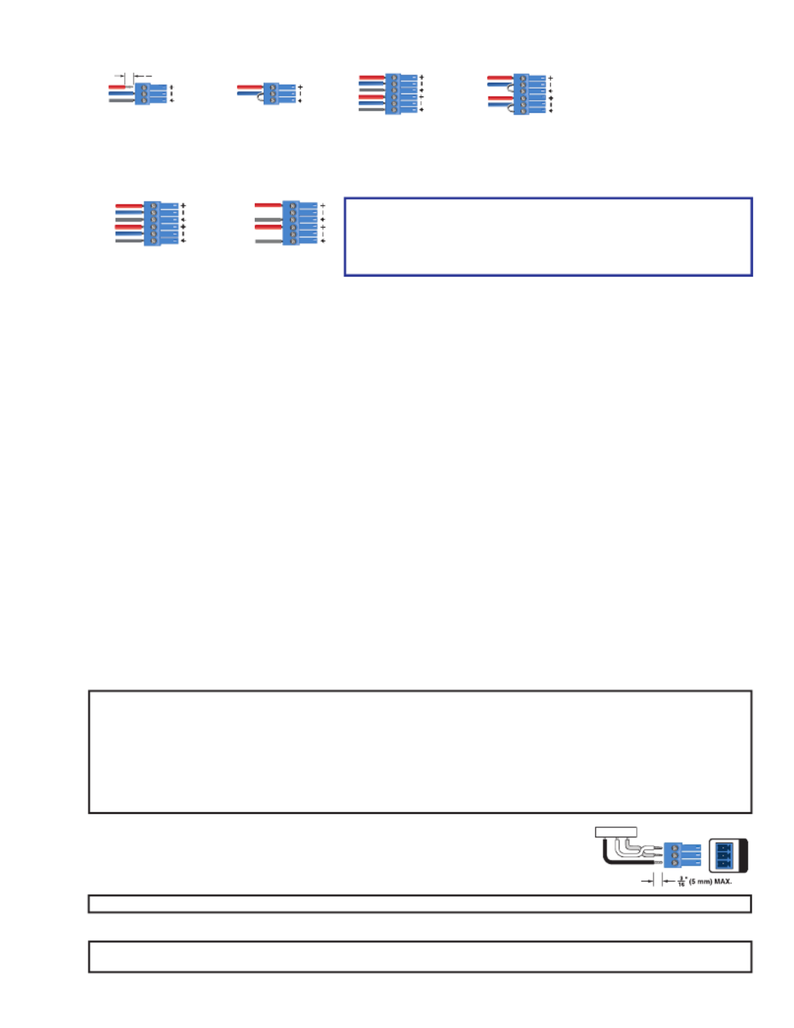
6-pole Audio INPUT Wiring
Balanced Input Unbalanced Input
Sleeve
Ring
Tip
Tip
Sleeve
Jumper
Tip
Sleeve
Jumper
Sleeve
Ring
Tip
3-pole Audio INPUT Wiring
Balanced Input
" (5 mm) MAX. (typ)
3
16
Sleev
e
Ring
Tip Tip
Sleeve
Jumper
Unbalanced Input
Figure 3. Balanced and Unbalanced Audio Input Wiring Diagram
L Line Out outputs 1 and 2 (see figure 2 on page 2) — Connect audio devices such as an audio L R amplifier or powered speakers
to the two 3.5 mm, 3-pole captive screw ports (see figure 4 to wire the connectors).
Balanced Input Unbalanced Input
Sleeve
Ring
Tip
Sleeve
Ring
Tip Tip
Sleeve
NO Ground Here
Tip
Sleeve
NO Ground Here
Figure 4. Audio Output Wiring
ATTENTION:
• For unbalanced audio OUTPUT, connect the sleeves to the ground
contact. DO NOT connect the sleeves to the negative (-) contacts.
• Pour la sortie audio asymétrique, connectez les manchons au contact au
sol. Ne PAS connecter les manchons aux contacts négatifs (–).
M Amp Output (IPCP A models only) — Connect passive speakers to this 5 mm, 4-pole captive screw port to receive an audio line input,
or a line input from the audio expansion bus. The selectable output modes of the amplifier are:
• • 2 x 100 watts @ 8Ω / 4Ω 1 x 200 watts @ 70 volts (Bridged)
• • 1 x 200 watts @ 8Ω (Bridged) 1 x 200 watts @ 100 volts (Bridged)
Control and Power
N IPCP Pro 360MQ xi control processor (IPCP A models only) — The Extron IPCP Pro 360MQ xi control processor card integrates
Ethernet connectivity into AV systems to allow users to remotely control, monitor, and troubleshoot AV equipment, including display
devices and switchers. The IPCP Pro 360MQ xi control card offers:
• IPCP Reset button and LED —
• Reset button — Initiates levels of control processor reset. For dierent reset levels, press and hold the recessed Reset
button while the switcher is running or while powering up.
• Reset LED — Indicates the level reset initiated on the control processor.
• COM1, COM2, and COM3 ports — Connect to the 5-pole COM port for both hardware and software ow control. Connect to the
3-pole COM ports for software ow control only.
• Digital I/O port — Congure each port as a digital input or output, with or without +5 VDC pull-up. Monitor or trigger events and
functions (toggle relays, issue commands, send e-mail), once congured.
• IR/Serial ports — Connect to the control processor to use infrared signals or unidirectional RS-232 serial signals to control various
devices via these ports. Set output signal type (IR or serial) during conguration.
• Relays ports — Connect devices for contact control.
• AV LAN Ethernet ports — Connect directly to the DTP3 CrossPoint.
• LAN Ethernet port — Connect the IPCP to an Ethernet network (for conguration and control of the IPCP and the devices
connected to it). Plug a cable into this RJ-45 socket and connect the other end of the cable to a network switch, hub, router, or PC
connected to a local network or the Internet
See the enclosed IPCP Pro Q xi and xi Series Setup Guide IPCP Pro Q xi and xi User Guide or the at www.extron.com to make all
connections and to congure and operate the IPCP Pro 360MQ xi control processor.
NOTES:
• The additional AV LAN ports function as multiport, unmanaged network switches for additional devices to connect to the same
network.
• If the DTP3 CrossPoint is connected via the front panel USB-C, the hardcoded IP address is 203.0.113.22.
• If connected to the rear panel AV LAN ports, the DTP3 CrossPoint default IP address is 192.168.254.254.
• If connected to the rear panel IPCP LAN port, the default IP address is 192.168.253.250.
• If the DTP3 CrossPoint IP address is changed, the AV LAN IP address (192.168.254.250) MUST be changed in Toolbelt to
the same subnet as the DTP3 CrossPoint in order to connect through the AV LAN port.
O Remote RS-232 port — Connect a serial RS-232 device into the matrix switcher via this 3.5 mm,
3-pole captive screw port for remote control of the switcher (see image on the right to wire the
connector).
P LAN (Ethernet) port (non-IPCP model) — (Optional) Connect a network WAN or LAN hub, a control
system, or a computer to the Ethernet RJ-45 port.
NOTE: The factory default IP address is 192.168.254.254.
TxGnd
RS-232 Device
Rx
Tx Rx
RS- 232
G
REMOTE
Q — CrossPoint switcher Reset button and LED
NOTE: The factory congured passwords for all accounts on this device have been set to the device serial number. In the event of
a complete system reset, the passwords convert to the default, which is extron for the and .Admin User
Produkspesifikasjoner
| Merke: | Extron |
| Kategori: | Bryter |
| Modell: | DTP3 CrossPoint 622 |
Trenger du hjelp?
Hvis du trenger hjelp med Extron DTP3 CrossPoint 622 still et spørsmål nedenfor, og andre brukere vil svare deg
Bryter Extron Manualer

7 Januar 2025
7 Januar 2025
7 Januar 2025
16 Oktober 2024
16 Oktober 2024
Bryter Manualer
- Bryter ORNO
- Bryter D-Link
- Bryter Apc
- Bryter Lancom
- Bryter IFM
- Bryter TP Link
- Bryter Totolink
- Bryter StarTech.com
- Bryter Yamaha
- Bryter Cudy
- Bryter Lindy
- Bryter Netgear
- Bryter Ecler
- Bryter Digitus
- Bryter Panasonic
- Bryter LevelOne
- Bryter Schneider
- Bryter EMOS
- Bryter CSL
- Bryter Smart-AVI
- Bryter Generac
- Bryter Dahua Technology
- Bryter Sonance
- Bryter Planet
- Bryter PCE
- Bryter Hikvision
- Bryter Equip
- Bryter Intermatic
- Bryter Speaka
- Bryter Nedis
- Bryter Alcatel
- Bryter Elation
- Bryter Logilink
- Bryter Leviton
- Bryter Advantech
- Bryter Atlona
- Bryter Jung
- Bryter Robbe
- Bryter Luxul
- Bryter Crestron
- Bryter INOGENI
- Bryter IPGARD
- Bryter Elektrobock
- Bryter PureLink
- Bryter Kramer
- Bryter ATen
- Bryter Blustream
- Bryter WHALE
- Bryter Tenda
- Bryter Suevia
- Bryter ZyXEL
- Bryter Homematic IP
- Bryter Vimar
- Bryter Setti+
- Bryter Trendnet
- Bryter Intellinet
- Bryter IOGEAR
- Bryter Fantini Cosmi
- Bryter Vemer
- Bryter Theben
- Bryter Alfatron
- Bryter Kaiser
- Bryter Finder
- Bryter Hager
- Bryter Kathrein
- Bryter DEHN
- Bryter Berker
- Bryter Adder
- Bryter Brilliant
- Bryter Roline
- Bryter HELGI
- Bryter QNAP
- Bryter DoorBird
- Bryter Ebara
- Bryter Rex
- Bryter Airlive
- Bryter PureTools
Nyeste Bryter Manualer
9 April 2025
6 April 2025
5 April 2025
5 April 2025
5 April 2025
3 April 2025
3 April 2025
2 April 2025
2 April 2025
2 April 2025